Welcome to my second blog! As I mentioned last time, I am going to go into some more detail about a project I have worked on this summer!
Since this summer has been flying by, I have already started and completed a few different projects. Most jobs I have done so far have been related to our Bleach Plant Project, but others have been just mill related.
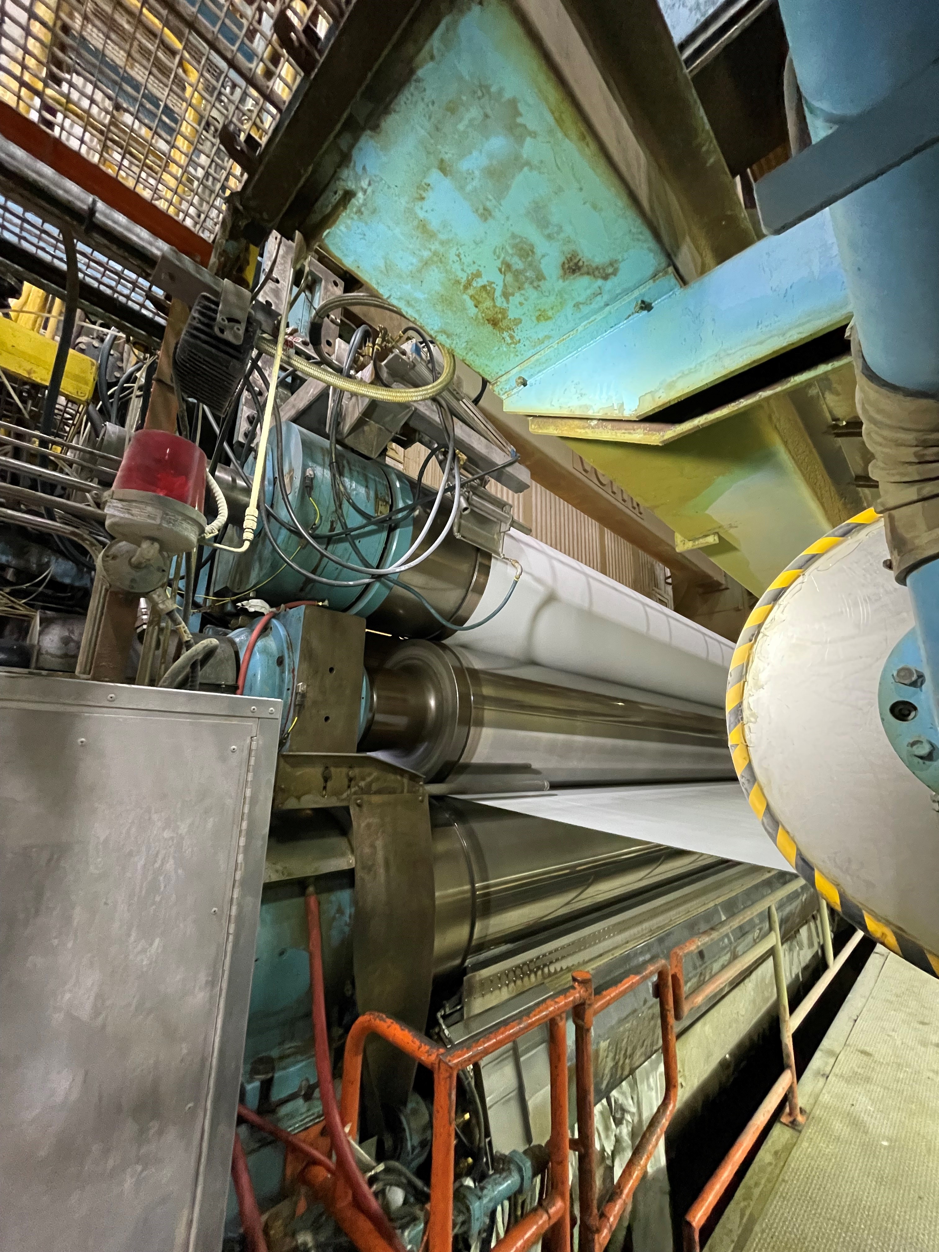
My first project I started working on was a winch pulling mechanism to separate the inside of a new roll from its shell. We need this new roll to be installed to our “Calander stack” so we can change the properties of our paper as it passes through. Bleaching our pulp allows us to create more varieties of paper, some of which require the different loading mechanism of this roll. Our current method of separating rolls for maintenance is no longer applicable for the new one so I was left with some inspiration to design a new system. Some of the guys toured a different mill a few months ago and took some pictures of their system which gave me a starting point. After that, I had to use what I’ve learned in school so far to make a solution.
During second year at school, we were taught how to use CAD software through a couple different courses. If you don’t know what CAD is, long story short its the software that engineers and others use to design parts and drawings for different structures and machines. In school I was taught how to use Solidworks which is a 3D CAD software to create different parts and assemblies. At ANC, we don’t use Solidworks but instead we use Inventor which is very similar. I then spent the next couple of weeks measuring up some of our current rolls to get an idea of dimensions.
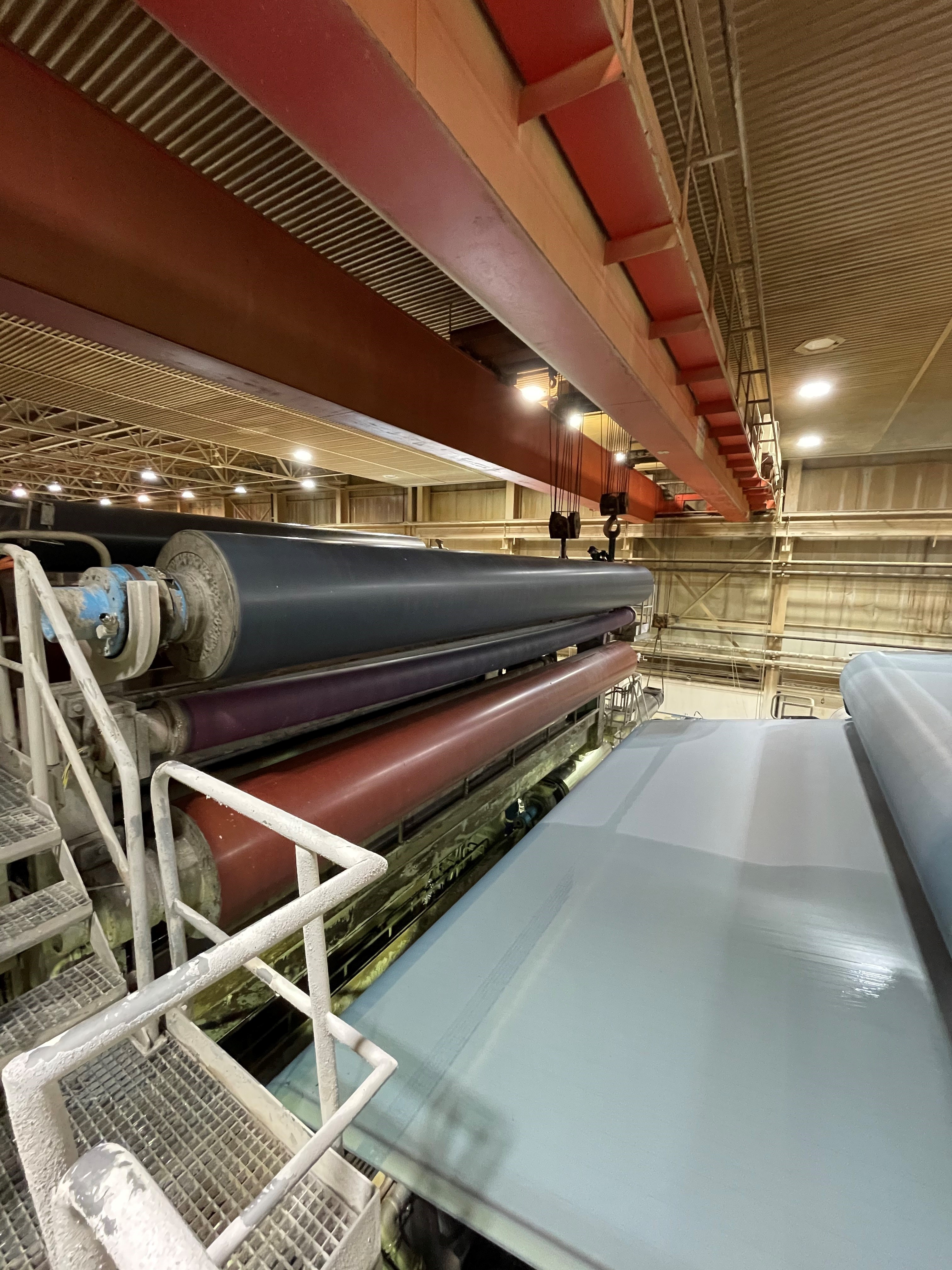
Fun fact, our rolls span the width of the paper machine, which is about 30 feet long. For reference, telephone polls are just over 30 feet long.
After a few weeks of designing, I came up with a full solution. To achieve my goal of being able to separate this roll I created 3 different components.
The first component I created was the winch cart. This winch cart is just an ordinary cart that has mount holes on its top plate for the winch, and some braces to pin against the strong back frames.

The second component is the strong back frames. These are two frames that are bolted to the ground for the winch cart to butt up against to pull the beam out of the shell.

The third component is the beam install cart. This is an ordinary cart as well that is used to create distance between the winch cart and the shell of the roll when installing the beam back into the roll.

This system probably seems very confusing, but I will try to explain it the best I can.
First, if you want to remove the beam (the inside of the roll) from the shell, you will place the roll about 40 feet away from the strong backs. Then you take the winch cart and butt it up against the strong backs. After that, you take the winch cable and string it out and hook it onto the beam and start pulling back which separates the beam from the shell. The shell doesn’t need to be braced back as the whole roll weights about 90 000 lbs, which is enough to hold it still.
Then if you want to install the beam back into the shell, you will roll the beam install cart out and pinch it between the winch cart and the shell with the beam on the other side. Then again you would string the winch cable through the shell and onto the beam and pull it back through.
That was probably very confusing, so here is a drawing of how it would look set up.

I hope I explained that good enough, but essentially, I was able to do some of my first engineering work through this job which is exciting!
Now that I got all the work stuff done, as a side note this past weekend I took a trip to Slave Lake with some of my friends and we went camping. We decided to try do some fishing but unfortunately we didn’t catch anything and decided to switch to wakeboarding and tubing quickly. It was a fun weekend!
That’s all I have for this week, thank you for reading!
Until next time,
Aaron





.jpeg)
